Frequency of Transition
The speed of an electronic device is its capability to follow, with its output, the variations of the input signal, as a function of the frequency of the latter. An effort towards the improvement of the maximum operational speed of organic field-effect transistors is crucial for many applications, e.g. for the pixel addressing electronics of flexible displays, radio frequency identification (RFID) systems for smart items identification or wireless communication. There exist several methods to characterize the maximum operational speed of a field-effect transistor (FET), yielding to different figures of merit. Among these, the transition frequency (fT), a small-signal figure of merit commonly adopted and widely accepted for the evaluation of a single device operational speed. It is defined as the unity gain frequency, i.e. the frequency at which the ratio of the absolute values of the small-signal AC gate current (ig) and the small-signal AC drain current (id) equals one. From its definition the analytical expression fT = gm/(2πCTOT) can be derived, where gm is the device transconductance and CTOT is the total capacitance. The previous formula for fT can be rewritten in order to highlight the main dependencies from the physical and geometrical parameters of the transistor, leading to:
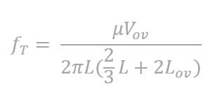
Where μ is the charge carrier mobility, Vov is the overdrive voltage, L is the channel length and Lov is the geometrical gate to source/drain overlap length.
The frequency of transition can be determined by directly measuring the gate current and the drain current as a function of the modulating frequency, and then by evaluating the fT as the crossing point between the two curves. This method is called direct measurement and it is the simplest one that can be implemented. Nevertheless, as fT is increasing and parasitisms make the direct measurement impossible at high frequencies, indirect measurement setups become mandatory for reliable measurements. During HEROIC project a scattering parameters (S-parameters) setup for transition frequency measurements has been employed. By using this method, output signals are measured as response to known input stimuli sent to the circuit, which is treated as a black box. This method is used to describe the small-signal response of nonlinear circuits but, the price to pay for using it, instead of performing a direct measurement, is a more complex measurement procedure.
Indeed, since most devices have non-coaxial interfaces, the DUT (Device Under Test) performances must be measured using a test fixture that interfaces the coaxial and non-coaxial transmission lines. In order to reliably measure the DUT, removing the effects of the test fixture from the measurement is crucial and can be achieved by performing a direct measurement calibration using well-known standards, which shifts the calibration plane to the probe tips. After calibration, the effects of interconnections between the probe tips and the actual device still affect the measurement. Therefore, a de-embedding procedure should be performed in order to remove those parasitic components. Generally, a model is assumed to describe them through a given number of parameters, which are then extracted by measuring the parameters matrix of test structures, e.g. open, short, or thru standards, which should be as similar as possible to the actual interconnections between probe tips and devices. In this way, the effects of the interconnections between probe tips and the actual device can be removed mathematically. The actual parameters that enable high frequency measurements are the S-parameters. They are sets of parameters determined with resistive terminations, which obviate the difficulties involved in obtaining the broadband open and short circuit conditions and provide stable and reliable boundary conditions. S-parameters are defined to relate independent incident power waves to dependent reflected power waves, a and b respectively:
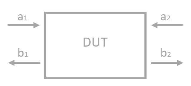 |
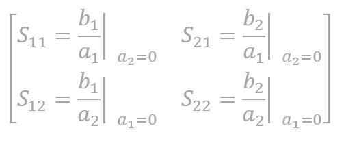
For a two-port device the relations reported below hold. In order to solve for the S-parameters of a network we need two linearly independent conditions for a1 and a2 and the most common consist in setting first a2 = 0 and then a1 = 0. This yields:
 |
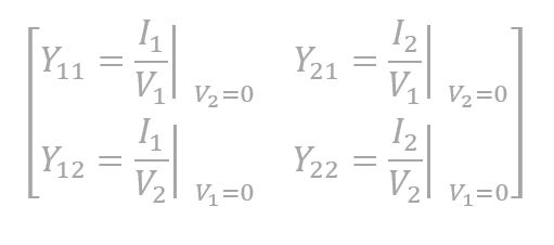
The S-parameters completely describe the network and once they are derived, other parameters such as admittance parameters (Y-parameters), impedance parameters (Z-parameters) and hybrid parameters (h-parameters) can be computed. Y-parameters relate the port currents and the port voltages trough the relationships reported below. In order to solve for the Y-parameters of a network we need two linearly independent conditions for V1 and V2 and the most common consist in setting at first V2 = 0 and then V1 = 0. This yields:
By applying these definitions, we easily find the relationships among the individual Y-parameters and the physical entities of the device:
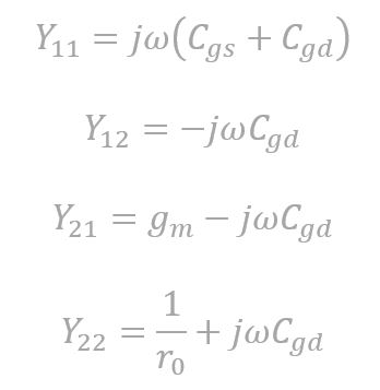 |
where Cgs and Cgd are respectively the gate-to-source and the gate-to-drain capacitances and r0 is the transistor output resistance. No single Y-parameter contains in itself the information about the fT of the device, therefore the latter has to be derived from different parameters. Among all the parameters one can measure, h21 is the one that contains the desired information. This can be shown starting from the relationships among h-parameters, port currents and port voltages. From these relations, the definition of individual h-parameters follows:
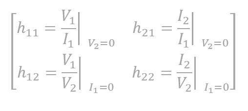
We finally notice that h21 is the transistor current gain with short-circuited output. From its definition and by recalling fT definition, we know that there is a strict relationship between these two. We can derive h21 expression by inspection or by noticing that h21 = Y21/Y11, and therefore:
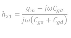
The magnitude of |h21| versus frequency therefore decreases by 20 dB/decade at low frequency and then flattens at high frequency, since at the frequency at which |h21| becomes unity typically ![]() , the proper fT can be extracted.
, the proper fT can be extracted.
More Information here